by Admin | Aug 15, 2019 | New Products, Our Instruments
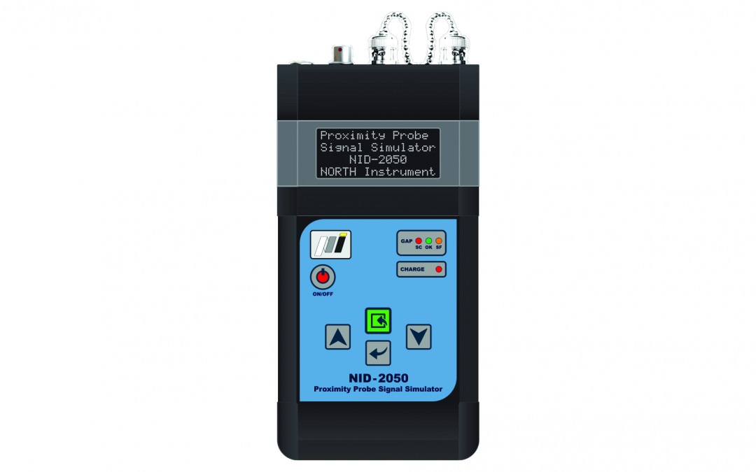
Description NID-2050 Proximity Probe Signal Simulator is a battery operated instrument which is used to electronically simulate outputs from various types of Proximity Probe Drivers. The device can be used as stand-alone device or it can be PC driven via embedded USB communication. In PC mode the device provides all the benefits of a stand-alone mode, with the difference that includes a number of useful tools that make it easier to use. Thus, for example, the software contains a database of Proximity Probes major manufacturers in the area of vibration and also has the option of “Customer defined”. By using the profile enables storing of data settings for future use. Application Note NID-2050 Proximity Probe Signal Simulator is suitable for checking and calibration measurement lines for dynamic and static parameters analysis. Gap function allows quick verification of Proximity Probe position against the target object. Device is especially optimized for Machinery Monitoring Systems (MMS). Features Datasheet Software User Manual Specification Simulates various proximity probes signal outputs Fully compliant with the requirements of ISO 20816 standards Operates in two modes: stand-alone and PC based The software includes a sensors/transmitters database Automatic creation of reports in PC mode enabled Menu-driven operation Multi language menu Metric and Imperial units PC connection Battery operated NID-2050 Datasheet v1.0 – Letter ...
by Admin | Feb 22, 2019 | Our Instruments
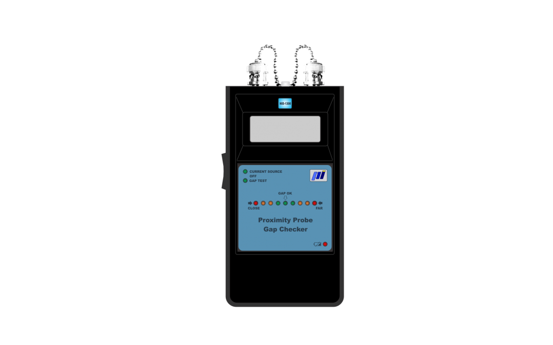
Description NID-1300 Proximity Probe Gap Checker is a battery operated, easy to use instrument that is used to check proximity probe GAP which is indicated on LED bar integrated on top panel. There is also an LCD display for reading GAP voltage for better accuracy. NID-1300 also can be used as 2 wires loop powered DC constant current source of 12.0 mA. Power is supplied from one internally mounted 9V Alkaline battery. There is also a LED indication of Low Battery state. Operating modes can be selected by a slide switch mounted on the left side. There is also a visual identification of the selected mode placed on the top panel. In the middle position of the slide switch, device is Off. In GAP TEST mode, NID-1300 is measuring a GAP voltage on Proximity Probe Proximitor’s buffered output. Measured voltage is displayed on LCD screen and on LED bar, which indicates position of proximity probe. This system enables easy adjusting of proximity probe position using LED bar indicator. It is especially designed for fast check and adjustment of proximity probes positions in monitoring systems. It also helps the operator to adjust proximity probe optimal position and/or to get information about distance between proximity probe and the shaft. In CURRENT SOURCE mode, the instrument produces constant current of 12.0 mADC. It is designed to simulate 2 wires Loop powered constant current transmitters, which requires external power supply of 18 … 30V DC. Features Datasheet Software User Manual Specification Proximity Probe GAP checker 2 wires Loop powered constant current DC source Easy to use LCD for reading measured GAP voltage...
by Admin | Feb 21, 2019 | Our Instruments
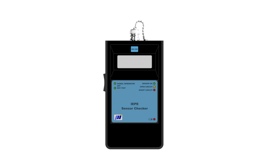
Description NID-1200 IEPE Sensor Checker is a battery operated, easy to use instrument that is used to check sensor condition by measuring DC Bias voltage and to electronically simulate IEPE (ICP®) sensor output. Power is supplied from one internally mounted 9V Alkaline battery. There is also a LED indication of Low Battery status. Operating modes can be selected by slide switch mounted on the left side. There is also a visual identification of the selected mode by LEDs placed on the top panel. In the middle position of the switch, device is Off. In BOV TEST mode, user can read measured DC Bias Voltage on display and check the sensor status by LEDs on the top panel. There are three predefined sensor statuses which depends on the Bias Voltage: SHORT CIRCUIT, SENSOR OK and OPEN CIRCUIT. Short Circuit LED is lit if the measured bias voltage is below 7V. Open Circuit LED is lit if the measured bias voltage is more than 15V. Sensor Ok LED is lit if the measured bias voltage is between 7V and 15V. If the customer needs different voltage limits, changes can be done free of charge, before the shipment. In SIGNAL GENERATOR mode, instrument supplies fixed frequency sinusoidal signal (100.0 mV RMS, 160.0 Hz) to simulate IEPE (ICP®) sensor output. Features Datasheet Software User Manual Specification IEPE (ICP®) sensor BOV(Bias Output Voltage) test IEPE (ICP ) sensor simulator (100.0mV RMS, 160Hz) Easy to use LCD for reading measured voltage LED indication of sensor status Slide switch for operating modes selection Empty Battery Detection NID-1200 Datasheet v1.0 – Letter Inputs –...
by Admin | Feb 20, 2019 | Calibration Instruments, Our Instruments, Sensor Simulators
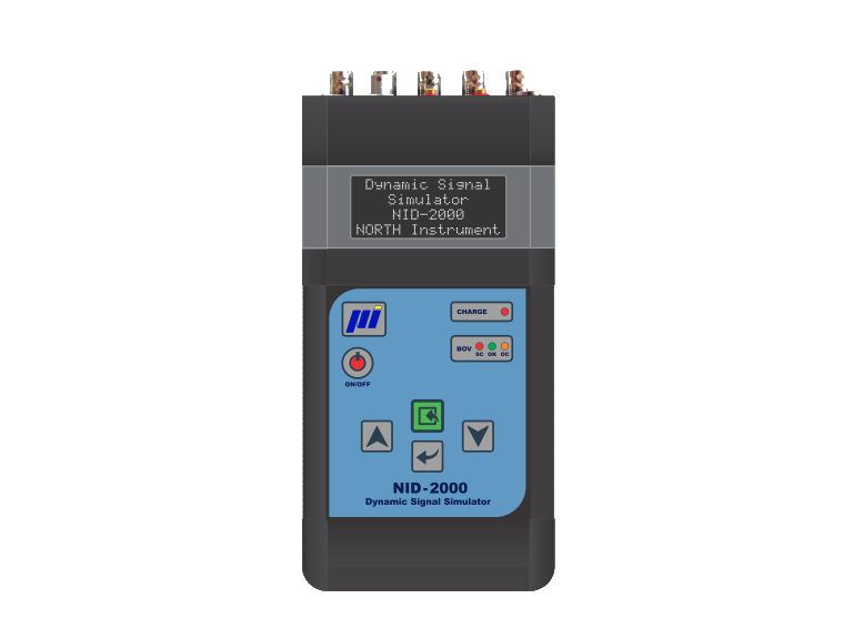
Description NID-2000/NID-2000P Dynamic Signal Simulator is a battery operated instrument that is used to electronically simulate variety of outputs from various types of sensors. This device uses a menu-driven 4×16 character LCD display to establish appropriate settings. NID-2000P Precision Dynamic Signal Simulator is precision version of NID-2000 Dynamic Signal Simulator (please see datasheet). The key panel contains five sealed switches marked with arrows, Enter (green button), Back and ON/OFF. Power is supplied from 4 AA rechargeable, internally mounted Ni-MH batteries which can be recharged with a regulated 9Vdc source. Connection to PC is established over the front mounted LEMO connector. PC mode will be automatically started after inserting proper cable into device. Output signal is user selectable from: single-ended voltage (mV), single-ended charge (pC), differential charge (pC), current-sinking IEPE (ICP®), loop powered current source (mA), tachometer (TTL), flow (TTL), OSO® (Optical Speed Output) and BOV (Bias Output Voltage). Frequency range is 1Hz to 10kHz; RMS output voltage is from 10mV to 10V or 10pC to 10.000pC. Outputs can be provided in acceleration, velocity, displacement, voltage or charge. Application note Suitable for inspecting measurement lines according to ISO 10816 standards. Device is especially designed for Condition Monitoring Systems (CMS) and/or Vibration Monitoring Systems (VMS) that are independent or connect to SCADA/DCS Systems. Features Datasheet Software User Manual Specification Price Simulates various sensor and transmitter signal outputs Fully compliant with the requirements of ISO 10816 (ISO 20816) standards Operates in two modes: standalone and PC based The software includes a sensors/transmitters database of the major manufacturers Automatic the creation of reports in PC mode enabled Loop powered current source output Tachometer TTL...
by Admin | Jan 18, 2019 | Other Products, Our Instruments
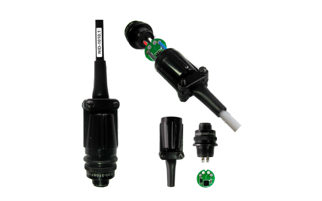
Description NID-1010.1 Integrated TEDS* Adapter (with MIL connector) is an electronic device that enables conversion from non-TEDS IEPE (ICP®) sensors into TEDS IEPE (ICP®) sensors according to ISO/IEC/IEEE 21451-4:2010 standard. This device allows the user to read/write such data as identification data about manufacturer, identification data concerning the sensor, sensor’s technical characteristics, details regarding calibration etc. This device is made for connection to IEPE piezoelectric accelerometers and IEPE piezoelectric velocity sensors, which have two pin connector compatible with the MSL-DTL-5015 (formerly MIL-C-5015). With this unit, we offer two types of low noise cables suitable for IEPE (ICP®) sensors: cables with armor and without it. Type and length of low noise cable is user definable during the ordering process. Standard cable lengths are: 3ft, 6ft and 10ft. There is a possibility of ordering any length of cable as long as it has no interference with IEPE (ICP®) signal. Reading and writing data are possible with any reader/writer that is fully compatible with ISO/IEC/IEEE 21451-4:2010 standard. Optionally, we offer the NID-1001 TEDS Interface Kit with related software for writing and reading of TEDS data. Application note It is possible to install and implement the unit both in a new, as well as in the existing Condition Monitoring Systems (CMS) and Machinery Monitoring System (MMS), that are independent and/or SCADA/DCS supported. ___________________ * Transducer Electronic Data Sheet (TEDS) contains critical information needed by an instrument or measurement system to identify, characterize, interface and properly use the signal from an analog sensor. For more details see ISO/IEC/IEEE 21451-4:2010 standard. Features Datasheet Software User Manual Specification Transforms non-TEDS IEPE sensor into TEDS...
by Admin | Jan 24, 2018 | Other Products, Our Instruments
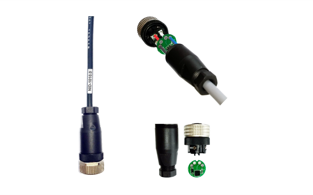
Description NID-1010.0 Integrated TEDS* Adapter (with M12 connector) is an electronic device that enables conversion from non-TEDS IEPE (ICP®) sensors into TEDS IEPE (ICP®) sensors according to ISO/IEC/IEEE 21451-4:2010 standard. This device allows the user to read/write such data as identification data about manufacturer, identification data concerning the sensor, sensor’s technical characteristics, details regarding calibration etc. This device is made for connection to IEPE piezoelectric accelerometers and IEPE piezoelectric velocity sensors, which have connector compatible with the IEC 60947-5-2 standard (Euro M12). With this unit, we offer two types of low noise cables suitable for IEPE (ICP®) sensors: cables with armor and without it. Type and length of low noise cable is user definable during the ordering process. Standard cable lengths are: 3ft, 6ft and 10ft. There is a possibility of ordering any length of cable as long as it has no interference with IEPE (ICP®) signal. Reading and writing data are possible with any reader/writer that is fully compatible with ISO/IEC/IEEE 21451-4:2010 standard. Optionally, we offer the NID-1001 TEDS Interface Kit with related software for writing and reading of TEDS data. Application note It is possible to install and implement the unit both in a new, as well as in the existing Condition Monitoring Systems (CMS) and Machinery Monitoring System (MMS), that are independent and/or SCADA/DCS supported. ___________________ * Transducer Electronic Data Sheet (TEDS) contains critical information needed by an instrument or measurement system to identify, characterize, interface and properly use the signal from an analog sensor. For more details see ISO/IEC/IEEE 21451-4:2010 standard. Features Datasheet Software User Manual Specification Price Transforms non-TEDS IEPE sensor into TEDS sensor...
